1. Who this page is for
Ansible… Puppet… NETCONF… Yang Models… Python… Jinja templates… NAPALM… Automation … Infrastructure-As-Code - if you’re a Network Engineer, chances are you’ve heard these terms tossed around in your professional circles over the last few years. And if you’re a Network Engineer like the ones I know, you’re an expert at understanding and building networks, but find yourself at a disadvantage when talking about automation. You’re a hands-on person and like things explained bottom-up.
If this describes you, this article is for you.
2. “Network Automation” - the term
Network Automation revolves around the practice of having software configure your network devices - as opposed to you having to manually log on to each device and write lines of text or edit files on that device.
Of course there’s a lot more to Network Automation than this, but this is the central idea.
The benefits of having software configure your network are obvious: repetitive tasks can be performed without human fatigue or human error, configuration changes can be pushed out much faster and with more predictable results, and it gives you the opportunity to integrate with other IT workflow tools (like Change Management,
3. What is this article describing?
Software to configure networks sounds great, but what is it that you, the network administrator, have to do for driving this software? After all, obviously, you have to provide your intention in some form (“create this new SSID”, “add this new ACL on all access ports”, “reserve some bandwidth for video on all links”, and so forth).
How exactly you indicate your “intention” varies depends upon the exact software technology and application you choose, and this is going to be the focus of the rest of this article.
The goal of this article is to provide a “1000-feet” view of the Network Automation landscape. By “1000-feet” I mean that I am not going to give you a 30,000-feet level, comprehensive-yet-incomprehensible story filled with terminology, nor am I going to just point you at a bunch of GitHub code repositories and send you on your way.
What we do, instead, is take a specific real-life scenario that network administrators are intimately familiar with, and study how this is handled using different network automation and configuration management software applications.
3.1 High-level and Low-level automation technologies
Software technologies that are associated with Network automation can be placed under two broad categories:
- Device Interfaces - what I call low-level technologies
- Configuration Management and Deployment systems - high-level technologies
3.1.1. Device interfaces
These are technologies that are concerned with connecting to the network device, gathering its state, and changing its state. There are two sub-categories here:
3.1.1.1 Text-based (“screen scraping”) interfaces
These are software interfaces that essentially mimic the human user: establish an SSH or telnet or serial line connection to the network device, then send text commands (e.g. “show inventory”), and then read (parse) the output printed by the device. Some examples in this category are:
- Python (with the Paramiko or Netmiko libraries) - we’ll be talking about this
- Expect
3.1.1.2 API-based (“programmability”) interfaces
These are non text-based interfaces found on some device models that allow external software to connect to the device and set/get its state using methods other than human CLI commands. The phrase Model Driven Programmability is sometimes used to describe these technologies. Some examples in this category are:
- NETCONF with Yang
- Cisco’s NX-API (for switches running NX-OS)
- Juniper’s PyEZ
Note on SNMP: SNMP would fall under the sub-category of a non text-based interface to access a device’s state. Over the many decades of its existence, though, the industry has used SNMP heavily for device monitoring but not so much to change the device’s state. For this reason this article will not talk about SNMP.
3.1.2 Configuration Management systems
The Device Interface technologies we spoke about in the previous section are low-level interfaces, in the sense that they take care of moving configurations (desired states) to the device, and in the reverse direction deliver the device status (operational state) back to the controlling station. You could regard them as merely “transport” mechanisms.
Configuration Management systems provide an additional layer of sophistication over and above simply pushing configurations and reading status. They provide formal mechanisms for:
- expressing the desired state of a device, usually using a language that is specific to the system (we’ll see examples of this below)
- maintaining and managing device configurations (as “recipes” or “playbooks”)
- maintaining an inventory of devices in a formal and standardized manner
Examples in this category are:
- Chef
- Puppet
- Ansible
One point to keep in mind about Configuration Management systems is that historically they were conceived and developed for automating IT systems, e.g. servers. None of them were specifically developed for automating network devices. This is a good thing, though - at a conceptual level, there is little difference between configuring the Apache web server on a bunch of servers, and configuring a QoS policy on a bunch of access switches. Having a single tool that does both therefore makes a lot of sense.
4. Example scenario
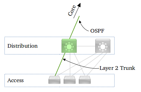
The figure above depicts a Distribution switch connected to several Access switches - this is a small segment of a typical 3-tier enterprise network, with layer-2 in the Access layer, and layer-3 in the Distribution layer.
Our case study is this scenario: a new VLAN, 220, has been created on the Access switch, and some ports on the Access switch have been assigned to VLAN 220. The trunk port has also been configured on the Access switch. All this has already been done.
Our job now is to configure the Distribution switch for this new VLAN 220. This involves executing the following steps (cisco devices assumed):
- Create the new VLAN
- Include this new VLAN in the list of VLANs carried by the trunk connecting to the Access switch
- Create an SVI (Layer 3 VLAN interface) for this new VLAN id
- Assign an IPv4 address to this SVI
- Include the newly created IPv4 subnet in OSPF
This scenario is a good example for demonstrating Network Automation because it is a typical operation that must be carried out repeatedly as and when new VLANs are added. The steps are simple enough, but susceptible to human error especially when executed by operations personnel with limited skill and experience.
5. Network Automation Infrastructure
To get started off on exploring networking automation and building proofs-of-concept, all you need is a Linux computer. A Linux VM on your laptop or workstation will work just fine. You will also need at least one network device to experiment with.
However this is a good time to understand and think about what formal deployments look like, and what infrastructure pieces are needed in a production environment.
The figures below depict a couple of typical setups:
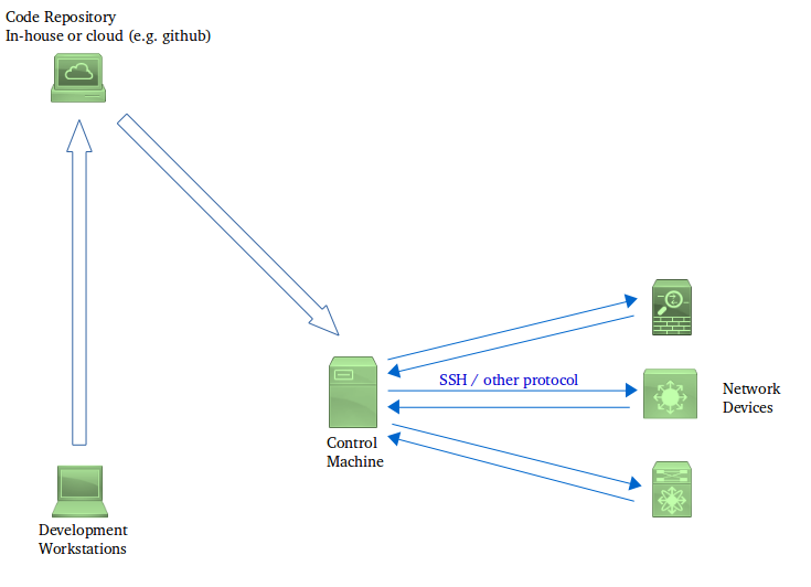
Developers write code (Python scripts, Ansible playbooks etc. depending on the technology chosen) at their workstations. At various defined milestones, they commit their code into a version-control system (which may reside in-house or may be something like GitHub).
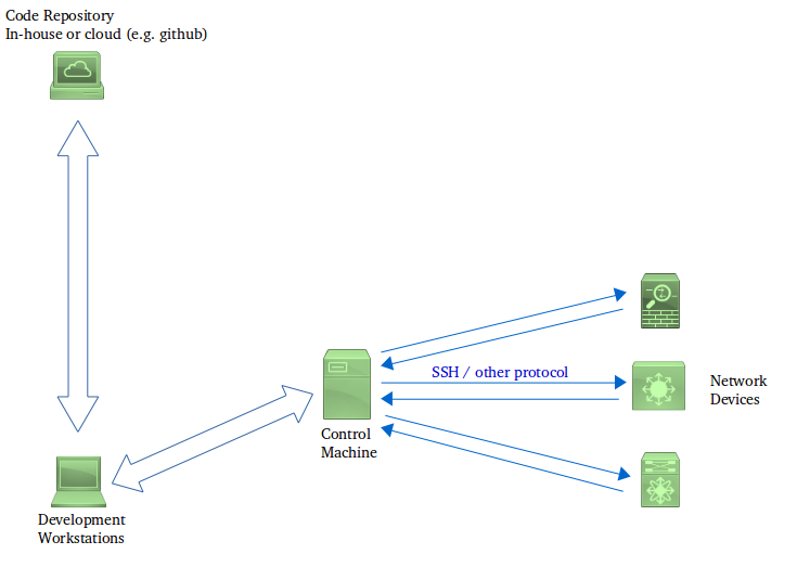
This code then “somehow” gets deployed on a Control machine - as in Model 1, the control machine can pull the code, or get the code pushed to it, directly from the repository. Alternatively, as in Model 2, a developer can first clone the repository on to their workstation and then deploy this clone to the control machine. The exact mechanism adopted depends, to some extent, upon the technology used (e.g. with Chef you have to use the figure 2 approach), and to some extent on the organization’s workflow practices.
The Control machine is typically a Linux server that has network connectivity to the management interfaces of the devices that need to be included inside the automation system. The Control machine also contains an installation of the software that will be used to run the automation code (e.g. Python with Netmiko, Ansible).
The Control machine then executes the automation software with the code written by the development team. The Control machine communicates to the network devices (switches, routers, firewalls etc.) in order to apply configurations and to read back the status, under the control of the automation software. This communication happens either using SSH, or using some proprietary protocol used by the automation software.
For simplicity the conceptual diagram does not depict separate Production and Test networks. In a real deployment, though, developers need a way to validate or test their code before a production roll-out.
6. Automating the example scenario
6.1 SSH using Python/Netmiko
The idea here is that you write a program that:
- establishes an SSH connection to the device
- sends configuration commands (just as a human user would)
- reads device status (typically by sending “show” commands just as a human user would)
- programmatically parses the status and uses that as a basis for program logic
You can use any programming language for this. One popular choice over the years has been Expect, which is an extension to the Tcl language. Owing to the growing adoption of Python in recent years, and the availability of the excellent Netmiko library, Python is the modern de facto choice.
Paramiko is a Python library that takes care of low-level SSH protocol operation (e.g. negotiating ciphers). Python programmers use Paramiko to implement SSH client and server functionality in their programs, for connecting to remote computers. Netmiko is a Python library that builds on Paramiko, and is specifically designed to provide SSH connectivity to network equipment from different manufacturers.
The fragment below shows Python code that uses Netmiko to establish an SSH connection to a Cisco IOS device:
netmiko_device_info = dict()
netmiko_device_info['host'] = '192.168.1.110'
netmiko_device_info['device_type'] = 'cisco_ios'
netmiko_device_info['username'] = login
netmiko_device_info['password'] = password
netmiko_device_info['secret'] = enable_password

device = Netmiko(**netmiko_device_info)
print('connected to device')

device.enable()
print('entered enable mode')

prompt = device.find_prompt()
print('device prompt is "{}"'.format(prompt))
The following code gets the current list of available VLANs on the device by sending the “show vlan brief” command to the device, and parsing (“scraping”) the result:
re_vlan_id = re.compile(r'^(\d+) .+$')

vlan_list = []

sh_op = device.send_command('show vlan brief')

for line in sh_op.split('\n'):
    match_obj = re_vlan_id.search(line)
    if match_obj:
        vlan_list.append(match_obj.group(1))

return vlan_list
The code above works because the program “knows” that the output of “show vlan brief” looks like this:
VLAN Name                             Status    Ports
---- -------------------------------- --------- -------------------------------
1    default                          active    Fa0/1, Fa0/2, Fa0/3, Fa0/4, Fa0/5, Fa0/6, Fa0/7, Fa0/8, Gi0/1
17   VLAN0017                         active
Note that the code above does the parsing of the output of the show commands manually, i.e. by employing Regular Expressions. Writing Regular Expressions isn’t everybody’s idea of fun, though, and not necessary either. There are projects like ntc-templates whose goal it is to save you the trouble of writing, maintaining and debugging regular expression code for processing the outputs of the most commonly used commands on the most commonly used Network Operating Systems from different manufacturers.
Sending a configuration command is equally straightforward with Netmiko. Here’s a code fragment that does this:
DESIRED_SETTINGS = {'vlan':      '220',
                    'ip':        '10.1.52.1/24',
                    'ospf_rtr':  '100',
                    'ospf_area': '0'}

# Convert the IP address to an 'ip_network' object
ip_network = ipaddress.ip_network(DESIRED_SETTINGS['ip'], strict=False)

# Generate the OSPF network statement
ospf_network_statement = ' network {} {} area {}'.format(str(ip_network.network_address),
                                                         str(ip_network.hostmask),
                                                         DESIRED_SETTINGS['ospf_area'])

# Generate the name of the SVI (VLAN interface)
svi_name = 'Vlan{}'.format(DESIRED_SETTINGS['vlan'])

# Now assemble the complete configuration from the above pieces of information
config_commands = []
config_commands.append('router ospf {}'.format(DESIRED_SETTINGS['ospf_rtr']))
config_commands.append(ospf_network_statement)
config_commands.append(' passive-interface default')
config_commands.append(' no passive-interface {}'.format(svi_name))
config_commands.append(' exit')

config_result = device.send_config_set(config_commands)
Upon execution, the code above sends the following configuration to the device:
router ospf 100
 network 10.1.52.0 0.0.0.255 area 0
 passive-interface default
 no passive-interface Vlan220
 exit
Notice how the user’s desired ip setting ‘10.1.52.1/24’ gets translated by the Python code to “10.1.52.0 0.0.0.255”, using the standard ip_address module. This is a demonstration of the power of automation - you could change the desired ip setting to, say, ‘10.1.52.155/28’ and the network statement will correctly get generated as ‘network 10.1.52.144 0.0.0.15 area 0’ without any need for human expertise, and without scope for human error.
Notice how the Python code above does NOT precede the configuration lines with “config terminal” (or “conf t”). This is because the underlying Netmiko implementation does that automatically (inside the call to send_config_set()) since we already told Netmiko earlier (when connecting to the device the first time) that the target device is a Cisco IOS device.
The full Python/Netmiko program for automating the example scenario in Section 4 above is on GitHub.
6.2 NETCONF
NETCONF is a protocol standardized by the IETF as RFC 6241. It specifies a protocol that runs between the control machine and the network device, and specifies methods for sending configurations to the device, reading status from the device, and handling notifications from the device. The desired configuration is NOT sent as configuration CLI lines; instead it is structured in some specific format which we will see shortly. Similarly status read back from the network device is also structured in a particular way, not as the output of a CLI “show” command.
The NETCONF protocol only specifies and defines the operations that the control machine can carry out (like get, get-config, edit-config, lock, unlock etc.), and the mechanism by which these operation requests are delivered to the network device. The NETCONF RFC does not define the contents of these requests themselves. That comes under the purview of YANG.
6.2.1 YANG
The data content accompanying a NETCONF operation follows what is called a YANG model, and is standardized by the IETF as RFC 6020. A YANG model describes a particular component of configuration data, like a VLAN or an OSPF router instance. Facts like “a permissible VLAN Identifier is an integer from 1 to 4094” and “an OSPF instance contains a list of networks” are encoded in formal language inside a file with a .yang extension. This file is then referred to as a “YANG model for VLANs” or “YANG model for OSPF”.
(If you are familiar with SNMP, at this time you’re probably thinking “so a YANG model is like a MIB” - and you’d be right. And NETCONF would be analogous to the underlying SNMP protocol.)
YANG model files are created and published by the IETF, and also by individual equipment manufacturers. As an example, look at the Cisco IOS XE YANG model for OSPF. Running the YANG file through the pyang utility provides a tree view of the model. The figure below is a partial, truncated view of this tree:
    module: Cisco-IOS-XE-ospf
      augment /ios:native/ios:router:
        +--rw ospf* [id]
           +--rw id                       uint16
           +--rw vrf?                     string
           +--rw address-family
              ...
    	  ...
           +--rw neighbor* [ip]
              ...
    	  ...
           +--rw network* [ip mask]
           |  +--rw ip      inet:ipv4-address
           |  +--rw mask    inet:ipv4-address
           |  +--rw area?   ios-types:ospf-area-type
           |           +--rw encrypted?    empty
           +--rw summary-address* [ip wildcard]
              ...
    	  ...
You can see a small part of the Cisco IOS XE YANG model for OSPF from that tree - an OSPF router instance has an ID, may have an associated VRF explicitly configured, has an address family, may have one or more neighbors explicitly configured, and may have one or more networks configured. Each network inside an OSPF router instance contains an IP address, mask and may have an area explicitly configured. Of course, this is only a tiny portion of the OSPF model.
That’s about the model. How this model is used to actually send configuration to a device is the subject of the next section.
6.2.2 Formatting configuration using NETCONF/YANG
All NETCONF operations (get-config, edit-config and so on) are formatted as Remote Procedure Calls (RPC) encoded in XML. On-the-wire data between the Control machine and the device looks like this (indentation added by me for clarity):
    <rpc ...>
     <edit-config>
      <target>
       <running/>
      </target>
      <config>
      ...                <--  CONFIGURATION DATA GOES HERE
      </config>
     </edit-config>
    </rpc>
The configuration data portion is also encoded in XML, and follows the YANG model. To take a specific example, the configuration data to add network 192.0.2.0/24 to OSPF instance id 101 in area 0 would look like:
 <native ...>
  <router>
   <ospf ...>
    <id>101</id>
    <network>
     <ip>192.0.2.0</ip>
     <mask>0.0.0.255</mask>
     <area>0</area>
    </network>
   </ospf>
  </router>
 </native>
6.2.3 Using Python to talk NETCONF: the ncclient library
ncclient is the library of choice for Python programs that need to use NETCONF. The library takes care of the NETCONF protocol-specific details (session setup, capability discovery etc.). The following example code sets up a NETCONF connection to a device and sends the YANG-modelled XML fragment that we wrote above (for adding 192.0.2.0/24 to OSPF instance id 101 in area 0):
from ncclient import manager

# Connect to the device
with manager.connect(host='10.10.20.100', port=830
                     username='whatever', password='whatever',
                     hostkey_verify=False, allow_agent=False,
                     look_for_keys=False) as m:

    print('Connected to device')
    print('Attempting to lock running config...', end='')

    with m.locked('running'):
        print('locked running config.')

        xml_snippet = '''
        <config xmlns:xc="urn:ietf:params:xml:ns:netconf:base:1.0"
                xmlns="urn:ietf:params:xml:ns:netconf:base:1.0">
         <native xmlns="http://cisco.com/ns/yang/Cisco-IOS-XE-native">
          <router>
           <ospf xmlns="http://cisco.com/ns/yang/Cisco-IOS-XE-ospf">
            <id>101</id>
            <network>
             <ip>192.0.2.0</ip>
             <mask>0.0.0.255</mask>
             <area>0</area>
            </network>
           </ospf>
          </router>
         </native>
        </config>'''

        print('changing running configuration...', end='')

        reply = m.edit_config(target='running', config=config_xml)

        netconf_reply_data = xmltodict.parse(reply.xml)['rpc-reply']

        if 'ok' in netconf_reply_data:
            print('success')
        else:
            print('failed')

    print('Unlocked running config')
print('Disconnected')
The full Python/ncclient code for automating the example scenario shown in Section 4 above is on GitHub.
6.3 Configuration Management Systems
All the three configuration management systems that we are looking at in this article (Chef, Puppet and Ansible) share some common characteristics, and in this section we will be looking at what they are.
6.3.1 Domain-Specific Languages (DSLs)
A Domain-Specific Language is the opposite of “general purpose programming language”, like Python. Unlike a general purpose language, a DSL is a programming language invented solely for use within a larger software application or tool. The syntax of DSLs is tailored to meet the requirement of the users of the application. Chef, Puppet and Ansible all use their own DSLs, as we will shortly see.
6.4 Chef
Chef is the first of the three configuration management systems that we’re going to be looking at. Remember that in this article we’re looking at things from a “1000-feet level”, so we will not go down to the level of installation and command-line details. We will however look at a workflow, and what the code that you will be writing looks like.
The topology of a Chef installation is similar to Model 2 discussed in the “Network Automation Infrastructure” section.
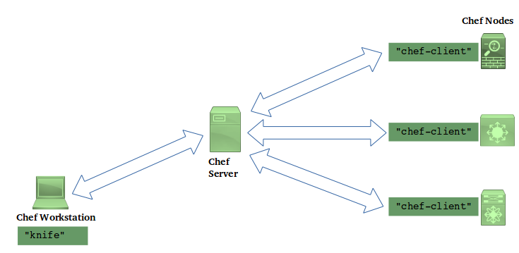
There are some things to note here:
- The managed nodes run Chef software, called
chef-client. This fact has an important impact on network devices. It means that Chef can only be used on devices that support an environment where chef-client is explicitly supported. - Workstations run Chef software (
knife) to talk to the Chef Server, and also to create cookbooks (more on this a little later, below). In other words, with Chef it is not just a matter of creating some files on the workstation and copying them over to the server by scp or rsync; the workstation is actually performs a functional role in the workflow.
The Chef workflow is like this, at a high level:
- Users on the Chef Workstation use the
knifecommand to create cookbooks, which in turn consist of recipes. A recipe is a sequence of configuration elements that declares things like “this VLAN should be present” or “OSPF is enabled “. Chef recipes are written in a DSL which is based on the Ruby programming language, plus language extensions to accommodate Chef functionality. - The
knifecommand also creates nodes (i.e. make a network device visible to the Chef server). - The node creation process involves associating a run-list with the node. The run-list is an ordered sequence of recipes that apply to that node.
- Once this association of a node with a run-list is made, the chef agent software running on each node pulls its configuration from the server. This is one of the salient features of Chef that needs some attention: nodes pull their configuration from the Chef server, compare the pulled configuration with the existing running configuration, and apply the pulled configuration only if it is different.
Client nodes can be asked to pull their configuration from the server periodically in an automated way, or the operator can trigger a pull.
Here is the Chef recipe that applies the configuration needed for our example scenario from Section 4:
Chef::Log.info('adding vlan 220 on distribution switch')

cisco_vlan '220' do
  action    :create
  vlan_name '3rd-floor-vendor-lab'
  shutdown  false
  state     'active'
end

cisco_interface 'Ethernet1/4' do
  description 'Downlink to 3rd floor'
  switchport_mode 'trunk'
  switchport_trunk_allowed_vlan '218, 219, 220'
end

cisco_interface 'Vlan220' do
  description         'vlan for 3rd floor vendor lab'
  shutdown            false
  ipv4_address        '192.168.220.1'
  ipv4_netmask_length 24
  svi_autostate       false
  svi_management      true
end

cisco_ospf 'main' do
  action :create
end

cisco_interface_ospf 'Vlan220' do
  action                         :create
  ospf                           'main'
  area                           1
  passive_interface              true
end
You will notice code paragraphs beginning with phrases like cisco_interface and cisco_vlan in the recipe above. In Chef parlance, these are called resources. The important point to note here is that these resources come from a cisco-cookbook created by Cisco Systems for NXOS devices. You need to install this cookbook in your setup before you are able to write recipes that use these resources. In other words, there is a dependence on vendor-provided software.
Cisco Cookbook on the Chef Supermarket Cisco Chef Cookbook on GitHub
6.5 Puppet
A Network Automation deployment that employs Puppet looks something like the following figure.
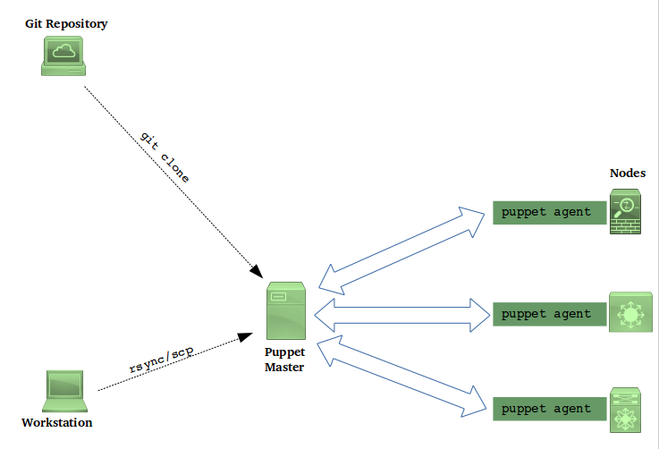
Managed nodes in a Puppet deployment run software called Puppet Agent. For this reason, in general only nodes that can explicitly support the Puppet Agent in their environment can be included into a Puppet deployment. (Having said that, Puppet has announced “agent-less” support for some Cisco devices - see here, but still that is a special case.)
Puppet nodes connect to the Puppet Master (using a proprietary protocol) and ask for (“pull”) their desired states (i.e. configuration). Upon receipt, the desired state is compared against the actual state of the node, and any changes are applied.
Puppet code takes the form of manifests written in the Puppet DSL. A Site Manifest is a list of things that need to be done at each site (i.e. node). For our example scenario, the site manifest contains this:
node 'dist_19_nxos_sjc' {
    class { 'dist_nxos::new_vlan':
        vlan_id => '221',
        vlan_name => '4th-floor-vendor',
        downlink => 'Ethernet1/4',
    }
}
The above code is saying this: on the node named dist_19_nxos_sjc (which is the name of a distribution switch), ensure that the dist_nxos::new_vlan class is applied, with parameters (vlan_id = '221', vlan_name = '4th-floor-vendor' and downlink = 'Ethernet1/4').
Classes in Puppet are blocks of code written, again, in the Puppet DSL. They consist of resources which essentially specify the desired state of the node. You (the programmer writing the automation code) are expected to create these classes (or leverage a class that someone else has already written).
The dist_nxos::new_vlan class is written by me for our example scenario, and looks like this:
class dist_nxos::new_vlan (
  $vlan_id,
  $vlan_name,
  $downlink,
) {
  require ciscopuppet::install

  cisco_vlan { $vlan_id :
    ensure    => present,
    vlan_name => $vlan_name,
    state     => 'active',
    shutdown  => false,
  }

  $svi_name = "Vlan${vlan_id}"
  $ipv4_address = "192.168.${vlan_id}.1"

  cisco_interface { $svi_name :
    ensure              => present,
    interface           => $svi_name,
    shutdown            => false,
    description         => "SVI for $vlan_name",
    mtu                 => 9216,
    ipv4_forwarding     => false,
    ipv4_address        => $ipv4_address,
    ipv4_netmask_length => 24,
    svi_autostate       => false,
  }

  cisco_interface { $downlink :
    ensure                        => present,
    shutdown                      => false,
    switchport_mode               => 'trunk',
    switchport_trunk_allowed_vlan => $vlan_id,
  }

  $ospf_name = "dist_vlans"
  $ospf_name_vrf = "${ospf_name}_default"

  cisco_ospf { "$ospf_name_vrf" :
    ensure => present,
  }

  $ospf_interface_name = "${svi_name} ${ospf_name}"
  cisco_interface_ospf { $ospf_interface_name :
    ensure => present,
    area   => 200,
  }
}
The code blocks beginning with cisco_interface, cisco_ospf etc. in the above code are pulling in “resources” to the node state definition. These resources come from modules written by the equipment vendor (Cisco in this case).
There is a Cisco Puppet Module Demonstration video on YouTube that is highly recommended if you’re looking to work with Puppet on Cisco NXOS devices.
6.6 Ansible
A typical Ansible deployment is depicted in the figure below.
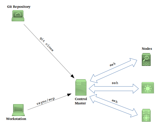
Comparing with the Puppet and Chef deployment figures in the previous sections, one significant difference leaps out: the communication between the Ansible Control Master an the managed nodes happens over SSH. There is no need for an agent to run on the node. This makes Ansible a more attractive choice for network devices.
The absence of an agent also means that Ansible nodes cannot initiate a “pull” of their expected state from the master. The configuration of a node is driven by a push from the Control Master, which in turn is triggered either manually or in an automated way based on some external trigger.
Ansible code is written in Ansible’s DSL, and is organized into playbooks. Playbooks contain one or more plays, and each play is in turn comprised of one or more tasks. A task uses a module to achieve a desired state on the managed node. The snippet below helps illustrate:
- hosts: distribution_switches
  tasks:
    - name: Ensure downlink interface is an L2 trunk, and is trunking the new vlan
      nxos_l2_interface:
        name: "Ethernet1/4"
        mode: trunk
        trunk_vlans: "220"
        state: present

    - name: Create the SVI
      nxos_interface:
        name: "Vlan220"
        admin_state: 'up'
        description: "L3 gateway SVI for 220"
        state: present
The above code snippet is extracted from a playbook. Every line beginning with the - hosts directive marks the beginning of a play, which is a sequence of common tasks applicable to a set of hosts. In our example, this play applies to a group of switches named distribution_switches. (These group names come from an inventory file elsewhere that lists out the nodes, their management IP addresses, their SSH usernames/passwords, the enable passwords and so on).
The play in the snippet above contains two tasks, the first of which configures the trunk interface, and the second configures the vlan (l3 routed) interface.
The nxos_l2_interface and nxos_interface lines in the tasks are module names. They come with the Ansible package distribution, and are created either by the equipment vendor or by the Ansible community. Each module has module-specific parameters like name and admin_state. The state parameter is a common parameter among many Ansible modules, and usually has possible values present and absent. A value of present is read as “make sure this is present”, and translates to “do this activity if it has not been done already”. Conversely, a state value of absent is read as “make sure this setting is absent”, and translates to “undo this thing”, i.e. “remove this configuration if it exists”. There are modules whose state parameters can have other values as well, such as “default”.
You can also write your own Ansible modules in Python if you find that none of the existing modules meets your purpose.
7. What do I use?
Like anything else (cars, vacations) the choice of an automation tool depends upon a number of factors, so we’ll just talk about those factors
High-level vs Low-level approaches
We discussed high- and low-level approaches in section 3.1. Low-level approaches (scrapers like Netmiko as well as model based approaches like NETCONF, Cisco NX-API, Arista eAPI, Juniper PyEZ) require you to write code in Python (other languages may be supported as well).
Writing infrastructure code in Python does give you a lot of flexibility - you can organize your data structures (like host definitions, port VLAN assignments, subnet assignments and so forth) in any way you like without being bound to something that a tool DSL might allow. Your program logic can also be as arbitrary as you like.
This flexibility however comes with a cost - maintainablity. In the absence of programming discipline and application of sound software engineering practices, you can very quickly end up with a huge mess of unruly code which no one (except, perhaps, the original coder) can understand. The low-level Python approach is fine for small, specific tasks with limited scope which cannot easily be achieved with a high level configuration management tool. For a scaleable and sustainable solution that manages your entire infrastructure, however, you would be well advised to go with a high-level configuration management tool.
Technical Feasibility
Some approaches may be simply impossible on some devices. For instance, the requirement to run an agent on the managed device makes it impossible to support agent-based technologies like Chef and Puppet on a number of network devices. Not all devices support model-based programmability interfaces. Even SSH may not be available all the time - for example, if you’re looking to do something at the device’s bootloader prompt.
Availability of talent
Whatever technology you adopt, you’ll have to pay for humans to write, test, debug, deploy and maintain automation code. You will probably find more Python programmers than Ansible programmers, and the number of programmers conversant with the Arista eAPI is likely to be minuscule. Which means that if you’re looking to manage Arista switches, you’re probably better off taking the Python or Ansible approach.
Existing tools already deployed
If your IT team is already using, say, Chef for automating server configuration, it makes a lot of sense to consider Chef for network automation as well, provided of course that this is technically feasible. This allows you to leverage existing infrastructure as well as technical expertise for your network automation.
Dependence on vendor and third-party offerings
While studying Puppet and Chef, we saw that their operation depend upon the existence of vendor-supported modules. This implies that the vendor’s support or commitment towards a particular technology becomes a factor. While making a technology evaluation, you’d have to check how often vendor modules are updated and upgraded, and in general whether the vendor is serious in providing support for that technology.
Who is winning in the marketplace
It is a fact of the technology world that as time progresses, some technologies gain strength and traction, some fall by the wayside, and there are always new things round the corner. The technologies that fall out of favour do not always do so on account of their technical merit: there are other factors like marketing and popular perception (not always fair) at play. As a technology evaluator, this is something you have to look for as well: obviously it is in your organization’s best interest to choose something that will stand the test of time - for as long as possible. The decision here is not always based on objective parameters.
A footnote on “Infrastructure-As-Code”
This is a term that is often tossed around and bears some explanation, especially for readers who are unfamiliar with the world of software engineering.
In software development, it is a common thing for several developers to be collaborating on building the product (which could be an app, an operating system, a library, a server, whatever). Programmers are responsible for writing and testing their individual pieces, which are then integrated at some point to build the final product. In this process, it is absolutely crucial that all programmers must put their code on to a common repository. Once the project reaches some reasonable level of maturity, it should be possible to build the final product from the repository.
This code repository therefore lies at the very heart of the process. And there are policies put in place around this repository: for example, no programmer is allowed to put (“commit”) their code into the repository without testing and review; there could be another policy that says that every commit to the repository must be immediately followed by an automated build of the entire product; there could be another policy that says that every commit to the repository must be followed by an automated test of the product to ensure that the last commit didn’t break any existing functionality. Software test teams are given specific points (“labels”) in the repository to work with, for testing purposes (as in “use label A for testing”, or “oh yes, that bug was found in label B, but is fixed in label E”, these labels being specific timestamps in the repository)
What has all this got to do with us? The fact that this notion of “The Repository” is now imported into the world of IT and Network Operations. Lets move from our 1000 feet level to a 10000 feet level and think about what the automation techniques that we spoke about in earlier sections are really doing. In the old days, routers/switches/firewalls/wireless controllers used to have configurations that only used to reside on the devices themselves, perhaps in flash memory. Likewise, server configurations would only reside in configuration files somewhere on the server’s file systems. With the introduction of automation tools, configurations now reside in central code repositories that are read by Ansible or Chef or whatever, and from there pushed to/pulled by the individual devices. Of course, for devices to work the configuration must be resident in flash, but the flash content is merely a copy of the repository; the repository is the “single source of truth”.
The fact that device and server configurations now reside in code repositories gives us the opportunity to borrow software engineering practices into IT and network operations. For instance, we could mandate that every commit to the repository (i.e. every change to the infrastructure) must be followed by running an automated test that pings critical devices and verifies the availability of all critical services.
This mindset that looks at device and server configurations (i.e. “infrastructure”) as software code is where the term IaS originates.
Conclusion and next steps
The Network Automation world is constantly evolving, and there are many things that I have not spoken about. I hope, though, that this whirlwind 1000 ft tour gave you the information that you need to get started, and you are now ready to find and take the next step.
The code for automating the example scenario is on GitHub.
If you have never worked hands-on on any automation technology before and are itching to get started somewhere, here’s what I would recommend:
- make sure you have a network device that you can experiment with
- install an Ubuntu Linux VM on your laptop (if you don’t already have a Linux workstation)
- follow the instructions to install Netmiko (do a web search)
- write a small Python program using Netmiko to get/set some basic information on your device
- then follow the instructions to install Ansible (do a web search)
- write a small playbook to get/set some basic information on your device